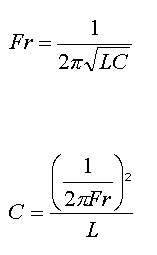
Hello, everyone! As most of you know, I moved to Los Angeles, CA. So naturally I had to give some things up like for instance my Tesla Coil.... This was a very sad time in my life considering that I put a lot of effort in to the design and construction of it. I would like to thank those that helped my and their contributions to the cause of science. Again thank you.... I hope to keep everyone updated on my progress out here in Los Angeles. Talk to you soon.
Sincerely,
Byron Logan Seabolt
byronseabolt@gmail.com
Wednesday, September 1, 2010
Thursday, May 13, 2010
Donation
Hello, everyone just a quick update. I have recently been trying to finalize school stuff. So, there has not been much involvement with the tesla coil but, a couple of good friends recently gave me some more tungsten rods and high voltage transformers for the spark gap/ input current. Which I have been needing so that I can run a series spark gap for tuning and quenching the gap. Also, to increase the input current to enhance the arch display. I would like to personally thank the ones for the donations and those who are following this blog. Thank you!
Sunday, April 25, 2010
Not a good start to saturday experiments!
Yesterday I had a not so great day starting out as far as experimenting goes. On friday one of my professors let me borrow his 15kva NST Transformer so that I could have more power. Then on saturday morning oh around 11am I hooked it up and the apparatus discharged one giant arc about 2.5 to 3 feet. There was a loud pop at the capacitor bank and the transformer went to crap. I did not compensate for the added voltage applied to the system.... A 150.00 lesson learned and the trust of a valued professor! Though the day became a little better when I received a little help from a friend Matt Gray. When we worked on tuning the spark gap and the primary capacitor bank. We were very successful and obtained at least 1.5 to 2 foot arcs also we could wirelessly light 40 watt florescent light bulbs at about 5 feet. Thanks Matt for your help.
Saturday, April 17, 2010
Working Tesla Coil apparatus
Video 1 is of the working Tesla Coil number 4. I had other models that did not work out so great. I will be posting them in due time and let you know what went wrong but, for now this a video worth displaying.
Tuesday, March 30, 2010
The Construction
In the following photos I had used gathered materials that could be found at the local hardware store and ebay was a huge help. I will include some websites that were also very helpful in the construction of my Tesla coil. The first photo has the naked secondary coil and the toroid that has not been constructed yet.

In Figure 1 I have the secondary coil. Also, I used my skateboard to attach the secondary in which I hand spun 1492 turns which took about 3 days and was very difficult. The dimensions of the secondary are 2.5 ft tall and 3 inches wide.
Figure 1
Figure 2 is the finished secondary coil. I used 24 gauge enamel coated copper wire that I bought off of ebay for about 32.00 dollars. There was 1600' on the spool.
Figure 2
Figure 3 is of the construction of the toroid which was supposed to act a as a capacitor and instead it was acting like a giant insulator. You can buy one of these on ebay which I recommend. The ebay store Tesla Stuff is where I found a lot of my equipment. Or, you can build one which really is about the same price. Just go to Home Depot or Lowe's and get air conditioning duct. Wrap it around an insulator like wood, which is a great insulator. Use a band saw or something to cut a circle at the desired width.
Figure 3
Figure 4 is of the stand which houses the entire apparatus. I was using a terrible design in the range of an old coffee table and in table to house the primary and secondary coil. Once I got enough money I purchased the wood for the correct housing. Using ideas off of the internet, I then crafted my own design.
Figure 4
Figure 5 is a close up shot of the primary holding slate. This was a very tedious job but, it worked out great. I used a band saw and hand drill. The holes are for using zip ties to hold the primary coil in place. So, if I really need to break it down, all that has to been done is cut the zip ties off.
Figure 5
Figure 6 shows the primary wound with about seven turns, also including a strike ring which was removed later. More coil has been added since this picture. There is 12 turns on the primary coil which is what I wanted to begin with.
Figure 6
Figure 7 is the secondary in place and it looks awesome. I have a one inch and a half inch ( 1.5" ) in a 360 degree radius gap between the secondary and the primary. Also, I drilled a hole for the earth ground wire for the secondary wire. This will allow for proper operation.
Figure 7
Figure 8 are the hand spun RF chokes. Using 24 AWG enamel coated copper wire and PVC piping. After hand winding the RF Chokes I coated them with polyurethane to hold the wire winding and protect it also. If you are wondering why waste you time building these two devices, well the RF Chokes help take out some of the high frequencies that are generated by the secondary on the input NST transformer or pig pole transformer.
Figure 8
Figure 9 is the high voltage wire that was used to wire all the components up for operation. I purchased this from the Tesla Stuff store on ebay. It works extremely well.
Figure 9

In Figure 1 I have the secondary coil. Also, I used my skateboard to attach the secondary in which I hand spun 1492 turns which took about 3 days and was very difficult. The dimensions of the secondary are 2.5 ft tall and 3 inches wide.
Figure 1

Figure 2 is the finished secondary coil. I used 24 gauge enamel coated copper wire that I bought off of ebay for about 32.00 dollars. There was 1600' on the spool.
Figure 2

Figure 3 is of the construction of the toroid which was supposed to act a as a capacitor and instead it was acting like a giant insulator. You can buy one of these on ebay which I recommend. The ebay store Tesla Stuff is where I found a lot of my equipment. Or, you can build one which really is about the same price. Just go to Home Depot or Lowe's and get air conditioning duct. Wrap it around an insulator like wood, which is a great insulator. Use a band saw or something to cut a circle at the desired width.
Figure 3

Figure 4 is of the stand which houses the entire apparatus. I was using a terrible design in the range of an old coffee table and in table to house the primary and secondary coil. Once I got enough money I purchased the wood for the correct housing. Using ideas off of the internet, I then crafted my own design.
Figure 4

Figure 5 is a close up shot of the primary holding slate. This was a very tedious job but, it worked out great. I used a band saw and hand drill. The holes are for using zip ties to hold the primary coil in place. So, if I really need to break it down, all that has to been done is cut the zip ties off.
Figure 5

Figure 6 shows the primary wound with about seven turns, also including a strike ring which was removed later. More coil has been added since this picture. There is 12 turns on the primary coil which is what I wanted to begin with.
Figure 6

Figure 7 is the secondary in place and it looks awesome. I have a one inch and a half inch ( 1.5" ) in a 360 degree radius gap between the secondary and the primary. Also, I drilled a hole for the earth ground wire for the secondary wire. This will allow for proper operation.
Figure 7

Figure 8 are the hand spun RF chokes. Using 24 AWG enamel coated copper wire and PVC piping. After hand winding the RF Chokes I coated them with polyurethane to hold the wire winding and protect it also. If you are wondering why waste you time building these two devices, well the RF Chokes help take out some of the high frequencies that are generated by the secondary on the input NST transformer or pig pole transformer.
Figure 8

Figure 9 is the high voltage wire that was used to wire all the components up for operation. I purchased this from the Tesla Stuff store on ebay. It works extremely well.
Figure 9

A little bit about myself
Hello, everyone my name is Byron I am an Electronic Engineering student at ITT Technical Institute. Now, for the past two years I have been studying continuously everyday mainly dealing with data transmission and energy distribution within an electronic circuit. The most intriguing aspect so far has been dealing with communications and sending electrical intelligence signals through the air on a carrier wave. I was even more intrigued when one of my professors started lecturing on resonant frequency.
This individual then started to talk about Nikola Tesla. I have been researching his work and his life since. This has lead me to my studies and work outside of school, which is understanding and experimenting with the process of generating high resonant frequencies and transmitting energy (current) through the air and energizing a device. I will try to up date this blog as much as possible with new pictures and videos displaying the calculations and demonstrations of this on going experiment.
This individual then started to talk about Nikola Tesla. I have been researching his work and his life since. This has lead me to my studies and work outside of school, which is understanding and experimenting with the process of generating high resonant frequencies and transmitting energy (current) through the air and energizing a device. I will try to up date this blog as much as possible with new pictures and videos displaying the calculations and demonstrations of this on going experiment.
Subscribe to:
Posts (Atom)

